Wave Interference and Standing Waves
When multiple waves propagate in a medium, interference takes place. Understanding how waves combine—sometimes enhancing and sometimes canceling each other—is essential for analyzing vocal tract resonance and the formation of formants.
Principles of Wave Interference
When two or more waves exist simultaneously in the same medium, the total pressure at any point is the sum of the individual wave pressures. This is called the principle of superposition.
Constructive Interference
Constructive interference occurs when waves combine to enhance the pressure disturbance:
-
Pressure peaks coincide in time or space
-
Amplitudes add: p_total = p₁ + p₂
-
Results in increased amplitude
-
Maximum when waves are “in phase”
Destructive Interference
Destructive interference occurs when waves combine to reduce the pressure disturbance:
-
Pressure peak of one wave coincides with pressure trough of another
-
Amplitudes subtract: p_total = p₁ - p₂
-
Results in decreased amplitude
-
Maximum cancelation when waves are “out of phase” by 180°
Clinical Note: Noise-canceling headphones use destructive interference, generating sound waves that are 180° out of phase with ambient noise to reduce perceived noise levels.
Standing Wave Formation
When waves of the same frequency travel in opposite directions, an interesting interference pattern develops. Two waves traveling in opposite directions can create the illusion of a standing wave as they interfere with each other.
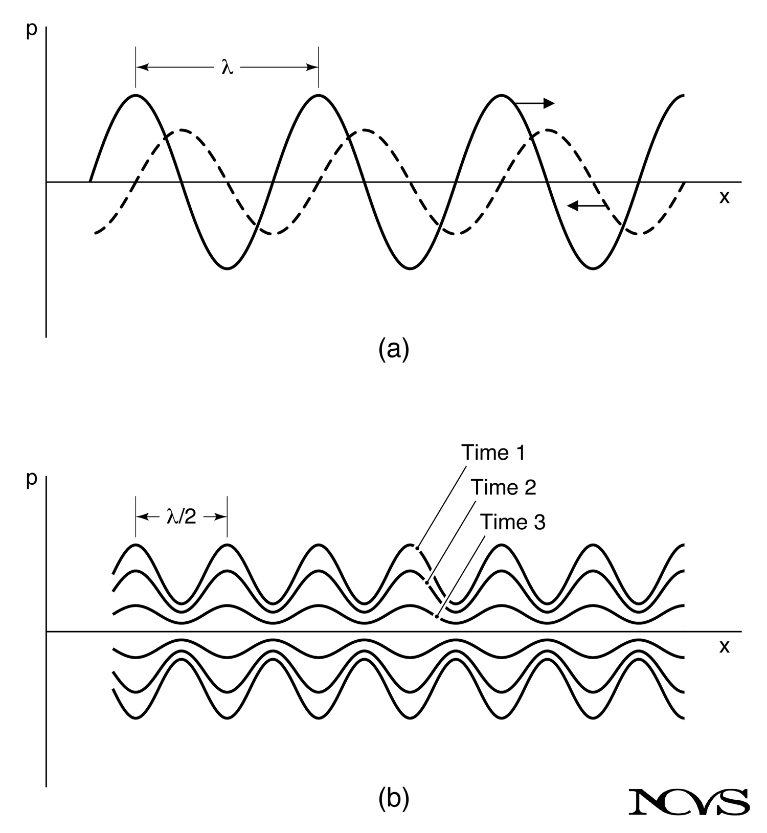
Figure 5.13: (a) Interference between a forward wave (solid curve) and a backward wave (dashed curve). The wavelengths are identical. (b) The corresponding standing wave pattern with snapshots taken at various instances of time.
Forward and Backward Waves
In Figure 5.13a, consider:
-
Solid line: Forward wave propagating to the right
-
Dashed line: Backward wave propagating to the left
-
Spatial representation: Distance x is independent variable, time is frozen
This situation is typical of an interference pattern resulting from reflection at a medium interface, where incident and reflected waves have:
-
Identical wavelengths (same frequency)
-
Different amplitudes (determined by reflection coefficient)
-
Opposite propagation directions
Time Evolution
Figure 5.13b shows the time-course of the interference pattern:
-
Successive “snapshots” are taken of the sum of the two pressures at each point x
-
Pressures periodically increase and decrease in time at all locations
-
At some locations, fluctuations are greater (peaks align constructively)
-
At other locations, fluctuations are smaller (peaks cancel destructively)
Standing Wave Pattern
A pressure sensor (microphone) responding to the absolute magnitude of fluctuations would detect a standing wave pattern:
-
Successive peaks (antinodes) and valleys (nodes)
-
Fixed positions in space
-
Separated by half wavelengths (λ/2)
Nodes and Antinodes
Definitions
Nodes:
-
Locations of minimum pressure fluctuation
-
When two waves of equal amplitude interfere, pressure is null at nodes
-
Occur at fixed spatial positions
-
Separated by λ/2
Antinodes:
-
Locations of maximum pressure fluctuation
-
When two waves of equal amplitude interfere, pressure is twice the individual wave amplitude
-
Occur at fixed spatial positions
-
Separated by λ/2
-
Offset from nodes by λ/4
Physical Interpretation
At nodes:
-
Incident and reflected waves always arrive out of phase
-
Destructive interference occurs at all times
-
Particle velocity is maximum (pressure minimum creates flow)
At antinodes:
-
Incident and reflected waves always arrive in phase
-
Constructive interference occurs at all times
-
Particle velocity is minimum (maximum pressure impedes flow)
Half-Wavelength Separation
Why are nodes (and antinodes) separated by half wavelengths rather than full wavelengths?
The answer lies in the relative propagation velocity between the two waves:
-
Forward wave moves at velocity +c (rightward)
-
Backward wave moves at velocity -c (leftward)
-
Relative velocity = c - (-c) = 2c
Because the waves approach each other at twice the normal propagation velocity, the spatial period of their interference pattern is halved:
$$\text{Node separation} = \frac{\lambda}{2} = \frac{c}{2F_0}$$
Standing Waves in the Vocal Tract
Standing wave patterns form in the vocal tract during phonation. These patterns of high and low acoustic pressure at fixed locations in the tract are likely to be sensed by the vocalist internally.
Resonance and Standing Waves
The vocal tract acts as an acoustic resonator:
-
Sound generated at the glottis propagates forward
-
Reflections occur at the lips (and other impedance discontinuities)
-
Forward and backward waves interfere
-
At resonance frequencies (formants), strong standing wave patterns form
Pressure Patterns
At formant frequencies:
-
Well-defined nodes and antinodes establish throughout the vocal tract
-
Node locations correspond to regions of high particle velocity (flow)
-
Antinode locations correspond to regions of high pressure, low flow
Example (first formant, F1 ≈ 500 Hz in neutral vowel):
-
Wavelength: λ = 343/500 ≈ 0.69 m
-
Quarter wavelength: λ/4 ≈ 0.17 m (about vocal tract length)
-
Standing wave pattern: pressure antinode at glottis, node near lips
Voice Placement Sensation
The standing wave patterns may constitute the basis for the perception of “voice placement”:
-
Vocalists report sensations of vibration or resonance in specific locations
-
These sensations likely correspond to pressure antinodes (high pressure regions)
-
Different vowels and pitches create different standing wave patterns
-
Training may enhance awareness of these internal acoustic patterns
Pedagogical Note: Voice teachers often refer to “forward placement,” “head voice,” or “chest voice.” These terms may relate to the vocalist’s perception of standing wave patterns in different regions of the vocal tract and head.
Mathematical Description
For a forward wave A sin(ωt - kx) and backward wave B sin(ωt + kx), where k = 2π/λ:
$$p = A\sin(\omega t - kx) + B\sin(\omega t + kx)$$
Using trigonometric identities, this can be rewritten as:
$$p = 2A\cos(kx)\sin(\omega t) \quad \text{(if A = B)}$$
This form explicitly shows:
-
Spatial factor: cos(kx) creates fixed nodes and antinodes
-
Temporal factor: sin(ωt) creates oscillation in time
-
The pattern does not propagate—it “stands” in place
Energy Considerations
In a standing wave pattern:
-
Energy is stored in the resonant system
-
Energy oscillates between kinetic (at nodes) and potential (at antinodes)
-
Energy is not transmitted along the tube (no net propagation)
-
Some energy is dissipated through losses (radiation, viscosity, heat)
The quality factor (Q) of a resonance relates to how much energy is stored versus dissipated per cycle. High Q resonances have:
-
Sharp, well-defined standing wave patterns
-
Low damping
-
High selectivity in frequency response
Sound Projection Clarification
As a final note on wave propagation and standing waves, it should be made very clear that sound cannot be “hurled” or “projected” as a projectile emerging from a firearm.
What “Projection” Really Means
When we say good vocalists “project” their sound, this can create misunderstanding:
Sound cannot be projected in the sense of:
-
Giving waves extra velocity
-
Pushing sound harder or farther
-
Creating directed beams (at normal vocal frequencies)
Effective projection actually involves:
-
Efficient acoustic impedance matching at the lips
-
Strong excitation of vocal tract resonances
-
Optimal source characteristics (glottal flow shape)
-
Appropriate formant frequencies for carrying over distance
Medium Control
Once the disturbance is created by the source, the medium takes over and propagates the disturbance in its own way:
-
The source cannot affect propagation velocity (c is determined by medium)
-
The source dictates frequency of periodic excitation
-
The source provides acoustic power, but the medium determines how it propagates
In periodic excitation (siren, vocal folds):
-
Source controls: F₀, spectral content, amplitude
-
Medium controls: c, characteristic impedance, propagation losses
-
Resonator controls: formant frequencies, bandwidths, radiation efficiency
Summary
Wave interference occurs when multiple waves exist simultaneously in the same medium, with their pressures adding algebraically. Constructive interference enhances amplitude when waves are in phase; destructive interference reduces amplitude when waves are out of phase. When forward and backward waves of the same frequency interfere, they create standing wave patterns with nodes (pressure minima) and antinodes (pressure maxima) separated by half wavelengths. In the vocal tract, standing waves form at resonance frequencies (formants), creating pressure patterns that vocalists may perceive as “placement” sensations. Understanding standing waves is essential for analyzing vocal tract resonance in the following chapter.
Key Takeaways
-
✅ Wave interference follows the principle of superposition: total pressure equals the sum of individual wave pressures
-
✅ Constructive interference (in phase) enhances amplitude; destructive interference (out of phase) reduces amplitude
-
✅ Forward and backward waves of the same frequency create standing wave patterns
-
✅ Nodes (pressure minima) and antinodes (pressure maxima) occur at fixed spatial locations
-
✅ Node and antinode separation is λ/2 due to relative velocity of 2c between opposing waves
-
✅ Standing waves form in the vocal tract at formant frequencies during phonation
-
✅ Vocalists may perceive standing wave patterns as “voice placement” sensations
-
✅ Sound cannot be “projected” like a projectile—propagation velocity is determined by the medium
Related Topics
Further Reading
-
Rossing, T. D. (1982). The Science of Sound. Reading, MA: Addison-Wesley.
-
Kinsler, L., & Frey, A. (1962). Fundamentals of Acoustics (2nd ed.). New York: Wiley.
-
Morse, P. M. (1947). Vibration and Sound. New York: McGraw-Hill.
-
Hall, D. E. (1980). Musical Acoustics: An Introduction. Belmont, CA: Wadsworth.