Reflection Coefficients
When sound waves encounter changes in the cross-sectional area of a tube, partial reflection occurs at the discontinuity. The reflection coefficient quantifies what fraction of the incident wave reflects and what fraction transmits through the junction. Understanding reflection coefficients is fundamental to vocal tract acoustics because area changes—at the glottis, tongue constrictions, and lip opening—create the multiple reflections that establish standing waves and formant resonances. These reflections transform the vocal tract from a simple conduit into an acoustic filter with characteristic frequency response.
The Physics of Acoustic Reflection
Acoustic reflection arises from impedance mismatches at boundaries between media or geometric discontinuities.
Impedance and Area Changes
Acoustic Impedance: The ratio of acoustic pressure to particle velocity, Z = p/u. For a uniform tube of cross-sectional area A:
Z = ρc/Awhere:
- ρ = air density (kg/m³)
- c = sound velocity (m/s)
- A = cross-sectional area (m²)
Impedance Interpretation: Impedance represents the “resistance” to acoustic flow. Narrow tubes have high impedance (high pressure required for given flow); wide tubes have low impedance.
Area Discontinuity: When tube area changes abruptly from A₁ to A₂, impedance changes from Z₁ = ρc/A₁ to Z₂ = ρc/A₂. This impedance mismatch causes reflection.
Reflection at a Junction
Consider a sound wave traveling in tube 1 (area A₁) toward a junction with tube 2 (area A₂):
Incident Wave: Pressure wave p⁺ travels toward junction with associated particle velocity u⁺.
Reflected Wave: Part of the wave reflects back into tube 1 as pressure p⁻ with velocity u⁻ (opposite direction).
Transmitted Wave: Part of the wave continues into tube 2 as pressure p₂ with velocity u₂.
Boundary Conditions: At the junction:
- Pressure continuity: p₁ = p₂ (pressure same on both sides)
- Volume velocity continuity: u₁A₁ = u₂A₂ (mass conservation)
These conditions determine the amplitudes of reflected and transmitted waves.
Pressure Reflection Coefficient
The pressure reflection coefficient r quantifies the amplitude of the reflected pressure wave relative to the incident wave:
r = p⁻ / p⁺Derivation: From boundary conditions:
r = (Z₂ - Z₁) / (Z₂ + Z₁)or in terms of areas:
r = (A₁ - A₂) / (A₁ + A₂)Range: -1 ≤ r ≤ +1
Sign Convention:
- Positive r (expansion, A₂ > A₁): Incident compression reflects as rarefaction
- Negative r (constriction, A₂ < A₁): Incident compression reflects as compression
- Zero r (no area change, A₂ = A₁): No reflection, perfect transmission
Transmission Coefficient
The transmission coefficient τ quantifies the amplitude of the transmitted pressure wave:
τ = p₂ / p⁺ = 1 + rRelationship to Reflection: The transmitted and reflected coefficients are not independent; they are constrained by energy conservation and boundary conditions.
Energy Considerations: The sum of reflected and transmitted acoustic power equals incident power (neglecting losses):
|p⁺|² = |p⁻|² + (A₂/A₁)|p₂|²Reflection at Common Boundaries
Specific boundary types in the vocal tract have characteristic reflection properties.
Open End (Expansion to Infinite Area)
The lip opening represents expansion from finite area A₁ to effectively infinite area:
Limit: A₂ → ∞, so A₁/A₂ → 0
Reflection Coefficient:
r = (A₁ - ∞) / (A₁ + ∞) → -1Meaning: Nearly complete reflection with polarity inversion. Incident compression reflects as rarefaction; incident rarefaction reflects as compression.
Pressure Boundary Condition: Pressure at open end must equal atmospheric pressure (zero gauge pressure), creating a pressure node.
Particle Velocity: Velocity at open end is maximum (velocity antinode), as air freely exits to atmosphere.
Practical Considerations: Lip radiation impedance is not truly infinite area; more accurately modeled as finite radiation impedance, giving r ≈ -0.9 to -0.95 at speech frequencies.
Closed End (Contraction to Zero Area)
The glottis, when closed, represents contraction to zero or near-zero area:
Limit: A₂ → 0, so A₂/A₁ → 0
Reflection Coefficient:
r = (A₁ - 0) / (A₁ + 0) = 1Meaning: Nearly complete reflection with same polarity. Incident compression reflects as compression; rarefaction reflects as rarefaction.
Pressure Boundary Condition: Pressure is maximum at closed end (pressure antinode), as air cannot flow through closed boundary.
Particle Velocity: Velocity at closed end is zero (velocity node), since air motion is blocked.
Glottal Opening: During phonation, glottis is partially open (small but non-zero area), giving r ≈ +0.8 to +0.95 depending on glottal opening.
Gradual vs. Abrupt Area Changes
The sharpness of the area transition affects reflection:
Abrupt Junction (step change over distance << λ):
- Reflection coefficient as calculated above applies
- Significant reflection occurs
- Creates well-defined discontinuity
Gradual Taper (change over distance ≥ λ):
- Reduced reflection compared to abrupt junction
- Wave “adapts” to changing area
- Approaches impedance matching
- Less standing wave formation
Vocal Tract: Most constrictions are intermediate—not perfectly abrupt but not very gradual. Typical tongue constrictions span 2-4 cm, intermediate between wavelength for low frequencies (λ ≈ 70 cm at 500 Hz) and high frequencies (λ ≈ 10 cm at 3500 Hz).
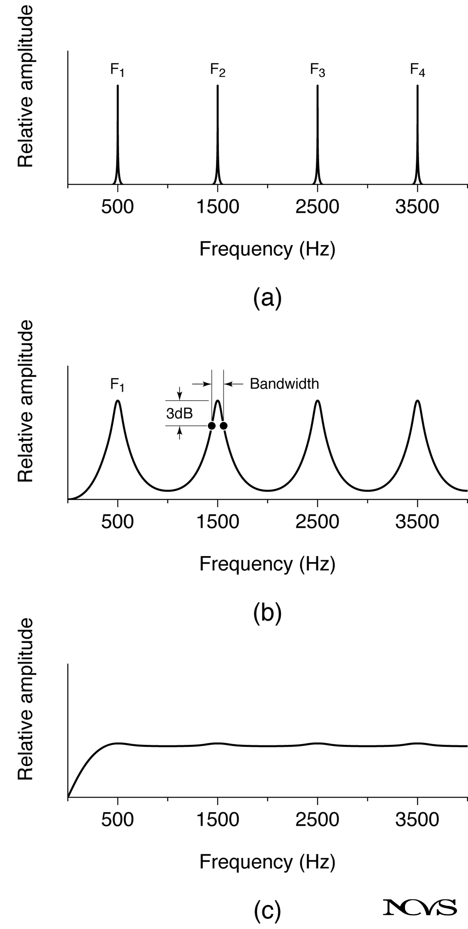 Figure 6.6: Reflection coefficients at area discontinuities showing positive reflection at constrictions and negative reflection at expansions.
Multiple Reflections and Standing Waves
Vocal tract resonances arise from multiple reflections between boundaries.
Two-Boundary System
The simplest resonating system has two reflecting boundaries (e.g., glottis and lips):
Wave Path:
- Wave originates at source (glottis)
- Travels to open end (lips)
- Reflects with coefficient r₂ ≈ -1
- Returns to closed end (glottis)
- Reflects with coefficient r₁ ≈ +1
- Repeats cycle indefinitely
Round-Trip Phase: After one complete round trip (distance 2L), phase change is:
φ = 2πf(2L/c) = 4πfL/cResonance Condition: Constructive interference (standing wave) occurs when round-trip phase is an integer multiple of 2π:
4πfL/c = nπ (n odd, for closed-open tube)Solving for frequency:
f = nc/4L (n = 1, 3, 5, ...)This derivation shows how reflection at boundaries creates the formant frequencies.
Effect of Non-Ideal Reflections
Real boundaries do not have r = ±1 exactly:
Finite Reflection: If |r₁| < 1 or |r₂| < 1, some energy is lost each reflection (transmission out of system or absorption).
Consequence: Standing waves decay over time rather than persisting indefinitely. This introduces damping.
Bandwidth: Formant bandwidth B is inversely related to reflection coefficient magnitude. Lower |r| (more transmission/loss) gives wider bandwidth:
B ∝ (1 - |r₁r₂|)Quality Factor: Q = F/B is higher for reflection coefficients closer to ±1 (sharper resonances).
Phase Considerations
Reflection coefficient has both magnitude and phase:
Complex Reflection Coefficient: r = |r|e^(iθ), where θ is phase angle.
Phase Change on Reflection:
- Expansion (r < 0): 180° phase change (π radians)
- Contraction (r > 0): 0° phase change
- Intermediate: Phase varies continuously
Resonance Frequency Shift: Non-zero phase (θ ≠ 0, π) shifts resonance frequencies from ideal values. This “end correction” accounts for reactance at boundaries.
Area Ratio and Reflection Magnitude
The area ratio A₂/A₁ determines reflection strength.
Quantitative Relationships
From r = (A₁ - A₂)/(A₁ + A₂), we can analyze:
A₂ = A₁ (no area change):
r = 0 (no reflection)A₂ = 2A₁ (doubling area):
r = (1 - 2)/(1 + 2) = -1/3 ≈ -0.33Moderate reflection with inversion.
A₂ = 4A₁ (quadrupling area):
r = (1 - 4)/(1 + 4) = -3/5 = -0.60Strong reflection with inversion.
A₂ = 0.5A₁ (halving area):
r = (1 - 0.5)/(1 + 0.5) = 0.5/1.5 ≈ +0.33Moderate reflection without inversion.
A₂ = 0.25A₁ (quartering area):
r = (1 - 0.25)/(1 + 0.25) = 0.75/1.25 = +0.60Strong reflection without inversion.
Threshold for Significant Reflection
Rule of Thumb: Significant reflection occurs when area ratio exceeds approximately 2:1 or falls below 1:2.
Vocal Tract Examples:
- Glottal area (0.1-0.2 cm²) vs. pharyngeal area (2-4 cm²): Ratio 10:1 to 40:1, giving r ≈ +0.8 to +0.95
- Constriction for /i/ (0.3-0.5 cm²) vs. adjacent pharynx (3-4 cm²): Ratio ~10:1, giving r ≈ +0.8
- Oral cavity (3-5 cm²) vs. lip opening (2-4 cm²) vs. external air (∞): Successive reflections
Reflection Coefficients in Vocal Tract Modeling
Reflection coefficients enable tube-based vocal tract models.
Concatenated Tube Model
The vocal tract can be modeled as many short cylindrical sections:
Tube Section n: Length Δx, area Aₙ
Junctions: Between sections n and n+1, reflection coefficient:
rₙ = (Aₙ - Aₙ₊₁) / (Aₙ + Aₙ₊₁)Wave Propagation: Waves propagate down tube, reflecting at each junction according to local reflection coefficient.
Transfer Function: Overall vocal tract response computed from cascade of reflections and transmissions.
Advantage: Can model arbitrary area functions A(x) by using many small sections.
Kelly-Lochbaum Algorithm
A classic digital filter implementation uses reflection coefficients directly:
Scattering Junctions: Each area discontinuity modeled as scattering junction with reflection coefficient rₙ.
Digital Delay Lines: Tube sections represented as delay lines with length corresponding to acoustic travel time.
Recursive Computation: Forward-traveling and backward-traveling waves computed recursively at each time step and junction.
Applications: Speech synthesis (formant vocoder), speech coding, vocal tract analysis.
Area Function Estimation
Given formant frequencies, inverse problem can estimate area function:
Forward Problem: Area function → reflection coefficients → transfer function → formants (straightforward).
Inverse Problem: Formants → transfer function → reflection coefficients → area function (ill-posed, non-unique).
Techniques: Optimization, linear prediction (reflection coefficients related to LPC coefficients), perturbation theory.
Clinical Use: Estimating vocal tract shape from acoustic measurements without imaging.
Boundary Conditions and End Corrections
Real boundaries have finite impedance requiring end corrections.
Radiation Impedance at Lips
The lip opening does not radiate into truly infinite space:
Radiation Impedance: Z_rad = R + jX, where R is radiation resistance and X is radiation reactance.
Low Frequency (ka << 1, where k = 2πf/c and a = lip radius):
Z_rad ≈ jωρπa²/c (reactive, inertial)High Frequency (ka >> 1):
Z_rad ≈ ρc (resistive, plane wave radiation)Transition: Around f ≈ c/(2πa) ≈ 1500-2000 Hz for a ≈ 1 cm.
End Correction: Acoustic “end” is not exactly at physical lip edge but approximately 0.6a beyond (adding effective length).
Reflection Coefficient: r varies from near -1 at low frequencies to somewhat smaller magnitude at high frequencies.
Glottal Impedance
The glottis is not perfectly closed even during “closed” phase:
Minimum Area: Small but non-zero (0.01-0.05 cm² during closed phase).
Time-Varying: Glottal area varies periodically during phonation cycle.
Effective Reflection: Time-averaged r ≈ +0.8 to +0.9 (not perfect +1).
Consequence: Some acoustic energy couples back to subglottal system; important for source-tract interaction.
Wall Compliance
Vocal tract walls are not perfectly rigid:
Yielding Walls: Tissue compliance allows wall motion in response to acoustic pressure.
Frequency Dependence: Low frequencies more affected (longer wavelength, more wall movement).
Acoustic Effect: Effective acoustic area slightly larger than anatomical area; reduces effective reflection coefficient magnitude.
Bandwidth Impact: Wall losses contribute to formant bandwidth, particularly for F1.
Clinical and Practical Implications
Understanding reflection coefficients informs various applications.
Vowel Production Efficiency
Optimal Reflection: Maximum acoustic output when reflection coefficients create strong standing waves at desired formant frequencies.
Constriction Strategy: High vowels with narrow constrictions create strong internal reflections (high |r|), producing well-defined formants.
Low Vowels: Less constriction, weaker internal reflection, somewhat broader formants but higher F1.
Nasal Coupling
Opening velopharyngeal port introduces side branch:
Acoustic Effect: Nasal cavity acts as side-branch resonator, creating:
- Additional reflections at velopharyngeal port
- Anti-resonances (zeros) where nasal cavity cancels oral cavity resonances
- Modified reflection coefficient at pharynx-oral junction
Nasalized Vowels: Changed reflection pattern alters formant frequencies and bandwidths, creating characteristic nasal quality.
Voice Prostheses and Amplifiers
Megaphone: Tapered horn gradually matches vocal tract impedance to free-field impedance, reducing reflection at mouth opening, improving radiation efficiency.
Electrolarynx: External sound source; vocal tract shapes spectrum but boundary conditions differ from normal phonation.
Tracheostomy: Changes glottal boundary condition; acoustic load on vocal folds altered, affecting vibration and acoustic output.
Singing and Voice Training
Resonance Optimization: Teachers guide students to optimize vocal tract shape for desired reflection pattern:
- “Forward placement”: May involve shaping oral cavity for favorable reflection patterns
- “Support the tone”: Maintaining appropriate subglottal pressure against glottal reflection
- “Open throat”: Reducing pharyngeal constrictions that create unwanted reflections
Formant Tuning: Systematic vowel modifications adjust reflection sites (tongue position) to alter formant frequencies for harmonic alignment.
Advanced Topics
Extensions of basic reflection coefficient theory address complex scenarios.
Frequency-Dependent Reflection
Reflection coefficients can vary with frequency:
Lossy Boundaries: Absorption at boundaries (particularly walls) is frequency-dependent, making r complex and frequency-dependent.
Reactive Boundaries: Impedance has reactive components (inertance, compliance), creating frequency-dependent reflection.
Consequence: Formant frequencies and bandwidths vary in complex ways; requires full frequency-dependent analysis.
Three-Dimensional Effects
Simple tube theory assumes one-dimensional wave propagation:
Cross Modes: At high frequencies (ka > 1), higher-order modes propagate across tube diameter, complicating reflection.
Non-Planar Waves: Wavefronts are not perfectly planar at area discontinuities.
Effect: Primarily affects F4 and higher formants; F1-F3 relatively unaffected in speech range.
Time-Varying Systems
Vocal tract geometry changes during speech:
Dynamic Area Function: A(x,t) varies with time, making reflection coefficients time-dependent.
Moving Boundaries: Tongue, jaw, lips move, changing reflection sites continuously.
Formant Transitions: Time-varying reflections create formant transitions that encode phonetic information.
Nonlinear Effects
At high sound pressure levels (loud voice), nonlinear effects emerge:
Nonlinear Propagation: High amplitude causes harmonic distortion during propagation.
Nonlinear Reflection: Reflection coefficients become amplitude-dependent.
Practical Range: Speech typically remains in linear regime; only extreme vocal effort enters nonlinear regime.
Summary
Reflection coefficients quantify the fraction of acoustic wave amplitude that reflects at area discontinuities in tubes, with the pressure reflection coefficient given by r = (A₁ - A₂)/(A₁ + A₂) where A₁ and A₂ are the cross-sectional areas before and after the junction. Positive reflection coefficients (r > 0) occur at constrictions where A₂ < A₁, with incident compression reflecting as compression; negative reflection coefficients (r < 0) occur at expansions where A₂ > A₁, with incident compression reflecting as rarefaction and polarity inversion. The extreme cases are the closed glottis (r ≈ +1, nearly complete reflection without inversion) and the open lip boundary (r ≈ -1, nearly complete reflection with inversion).
Multiple reflections between vocal tract boundaries create standing waves at frequencies where round-trip phase change satisfies resonance conditions, establishing formant frequencies. Non-ideal reflection coefficients (|r| < 1) introduce energy loss that creates finite formant bandwidths and determines resonance quality factors, with Q = F/B typically ranging from 7-20 for vocal tract formants. The magnitude of reflection depends on area ratio, with significant reflection occurring when area changes by factors of 2 or more.
Reflection coefficients enable computational vocal tract models including concatenated tube representations and the Kelly-Lochbaum digital filter algorithm, which computes wave propagation through cascades of scattering junctions. Practical applications include understanding vowel production efficiency through reflection patterns, analyzing nasal coupling effects, designing voice amplification systems, and informing singing pedagogy through resonance optimization. Realistic modeling requires considering frequency-dependent effects, radiation impedance at boundaries, wall compliance, and time-varying geometry during connected speech.
Key Takeaways
- ✅ Reflection coefficient r = (A₁ - A₂)/(A₁ + A₂) quantifies wave reflection at area discontinuities, ranging from -1 to +1
- ✅ Positive r (constriction) reflects waves without polarity inversion; negative r (expansion) reflects with 180° phase shift
- ✅ The glottis (r ≈ +0.8 to +0.95) and lips (r ≈ -0.9 to -0.95) create boundary conditions for standing wave formation
- ✅ Multiple reflections between boundaries establish formant resonances when round-trip phase satisfies constructive interference conditions
- ✅ Non-ideal reflections (|r| < 1) create energy loss determining formant bandwidth and quality factor Q
- ✅ Significant reflection occurs when area ratio exceeds 2:1 or falls below 1:2, typical of vocal tract constrictions
- ✅ Concatenated tube models use local reflection coefficients at each junction to compute overall transfer function
- ✅ Applications include vowel production analysis, nasal coupling effects, voice amplification design, and resonance optimization in singing
Related Topics
- Quarter-Wave Resonance
- Frequency Spectrum of the Resonating Tube
- Acoustic Impedance of Tubes
- Wave Interference and Standing Waves
- Reflection of Sound
- Three-Tube Approximation
Further Reading
- Fant, G. (1960). Acoustic Theory of Speech Production. The Hague: Mouton.
- Flanagan, J. L. (1972). Speech Analysis Synthesis and Perception (2nd ed.). New York: Springer-Verlag.
- Stevens, K. N. (1998). Acoustic Phonetics. Cambridge, MA: MIT Press.
- Titze, I. R. (2000). Principles of Voice Production (2nd ed.). Iowa City: National Center for Voice and Speech.
- Rabiner, L. R., & Schafer, R. W. (2010). Theory and Applications of Digital Speech Processing. Upper Saddle River, NJ: Pearson.
- Morse, P. M., & Ingard, K. U. (1968). Theoretical Acoustics. New York: McGraw-Hill.