Radiation from Simple Sources
Understanding how sound radiates from the voice requires first examining radiation from idealized simple sources. These theoretical models—particularly the monopole (point source) and dipole—provide essential insights into the directional patterns, efficiency, and frequency dependence of acoustic radiation that ultimately apply to the complex reality of speech and singing.
The Monopole (Simple Point Source)
The monopole represents the simplest theoretical sound source: a pulsating sphere of infinitesimal size that radiates uniformly in all directions.
Physical Model
Conceptual Description
- Imaginary sphere expanding and contracting radially
- Uniform surface velocity in all directions
- No preferred direction of radiation
- Creates spherical wave fronts propagating outward
- Also called “simple source” or “breathing sphere”
Mathematical Characteristics
- Volume velocity: rate of volume change (m³/s)
- Strength parameter: Q = volume velocity amplitude
- Radius assumed infinitesimally small
- Only property: magnitude of oscillation
- No directional characteristics in source itself
Radiation Pattern
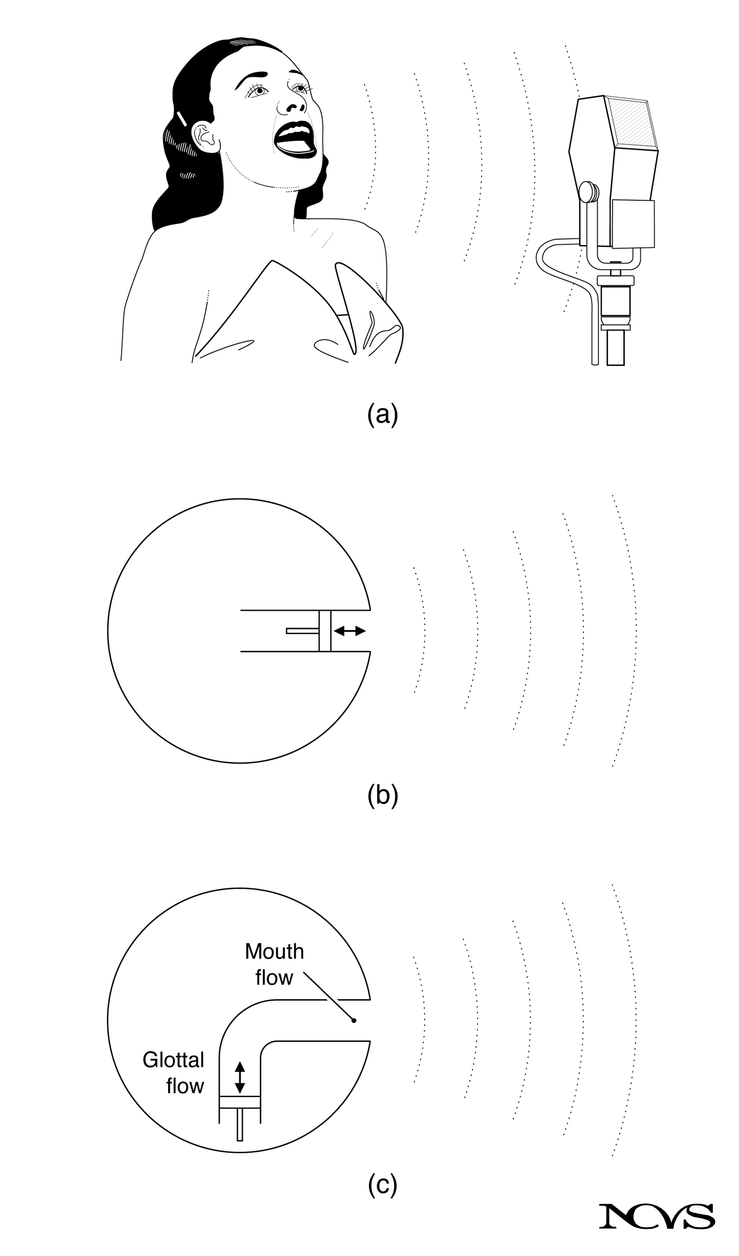 Figure 9.2: Radiation patterns showing omnidirectional monopole (spherical) and figure-eight dipole patterns in free space.
Omnidirectional Radiation
- Equal sound pressure at equal distances in all directions
- Spherical wavefronts expand uniformly
- Intensity decreases as 1/r² (inverse-square law)
- Pressure decreases as 1/r (inverse distance)
- No directivity: same output in all directions
Practical Implications
- Provides baseline for comparing directional sources
- Approximates radiation from small openings at low frequencies
- Useful for understanding far-field behavior
- Simplifies calculations of total radiated power
Acoustic Pressure from a Monopole
At distance r from a monopole source:
p(r,t) = (ρω²Q/4πrc) cos(ωt - kr)Where:
- p: acoustic pressure (Pa)
- ρ: air density (kg/m³)
- ω: angular frequency (rad/s)
- Q: volume velocity amplitude (m³/s)
- r: distance from source (m)
- c: sound velocity (m/s)
- k: wave number = ω/c (rad/m)
Key Observations
- Pressure proportional to ω² (frequency squared)
- Higher frequencies radiate more efficiently
- Pressure inversely proportional to r
- Phase lag kr accumulates with distance
Acoustic Intensity from a Monopole
The time-averaged intensity (power per unit area):
I = (ρω⁴Q²)/(32π²r²c)Important Features
- Intensity proportional to ω⁴ (frequency to fourth power)
- Extremely strong frequency dependence
- Intensity falls as 1/r² (inverse-square law)
- Total power independent of distance (power conserved)
Frequency Dependence Implications
- Doubling frequency quadruples pressure (12 dB increase)
- Doubling frequency increases intensity 16-fold (12 dB + 12 dB = 24 dB)
- Low frequencies radiate very inefficiently
- High frequencies dominate radiated sound
The Dipole Source
A dipole consists of two monopole sources of equal strength but opposite phase placed infinitesimally close together.
Physical Model
Conceptual Description
- Two point sources separated by small distance
- Equal strength but 180° out of phase
- One source expanding while other contracts
- Creates pressure/rarefaction pattern with directivity
- Also called “doublet” source
Physical Realization
- Approximated by vibrating sphere (front/back motion)
- Models sound from small vibrating surfaces
- Represents oscillating force in fluid
- Two sides of vibrating surface act as opposite-phase sources
Mathematical Representation
- Characterized by source strength (dipole moment)
- Dipole moment = source separation × monopole strength
- Limiting case: separation approaches zero
- Strength adjusted to maintain finite dipole moment
Radiation Pattern
Figure-Eight Pattern
- Maximum radiation along axis of dipole
- Zero radiation perpendicular to axis
- “Figure-eight” or “dumbbell” shape in 3D
- Front and back lobes of opposite phase
- Strong directivity even at low frequencies
Directional Characteristics
- Cosine directivity: pressure ∝ cos(θ)
- θ = angle from dipole axis
- At θ = 0° and 180°: maximum radiation
- At θ = 90° and 270°: zero radiation (null)
- Front/back lobes 180° out of phase
Acoustic Pressure from a Dipole
At distance r and angle θ from dipole axis:
p(r,θ,t) = (ρω²Qd cos(θ))/(4πrc) cos(ωt - kr)Where:
- d: effective dipole separation
- θ: angle from dipole axis
- cos(θ): directivity factor
- Other parameters as defined for monopole
Comparison with Monopole
- Additional cos(θ) term creates directivity
- Same frequency dependence (ω²) for pressure
- Same distance dependence (1/r) for pressure
- But different total radiated power
Acoustic Intensity from a Dipole
The time-averaged intensity:
I = (ρω⁴Q²d² cos²(θ))/(32π²r²c)Directional Features
- Maximum on-axis (θ = 0°, cos²(θ) = 1)
- Zero perpendicular to axis (θ = 90°, cos²(θ) = 0)
- Same ω⁴ frequency dependence as monopole
- But lower total radiated power (by factor related to (kd)²)
Comparison of Monopole and Dipole
Understanding the differences between these idealized sources illuminates voice radiation:
Directivity
Monopole
- Omnidirectional: uniform in all directions
- Spherically symmetric radiation
- No preferred direction
- Directivity index: 0 dB
Dipole
- Highly directional: figure-eight pattern
- Maximum on-axis, zero perpendicular
- Strong directional preferences
- Directivity varies with angle
Radiation Efficiency
Monopole
- Total radiated power independent of frequency (at constant Q)
- Actually, at constant amplitude: power ∝ ω⁴
- High-frequency radiation efficient
- Good radiator at all frequencies (relative to dipole)
Dipole
- Total radiated power reduced compared to monopole
- Cancellation between opposite-phase sources
- Efficiency proportional to (kd)²
- Very inefficient at low frequencies when kd << 1
Frequency Dependence
Common Features
- Both show pressure ∝ ω²
- Both show intensity ∝ ω⁴
- Strong preference for high frequencies
- Low-frequency radiation inherently difficult
Different Features
- Monopole total power independent of frequency (constant Q)
- Dipole total power additionally reduced at low frequencies
- Dipole has extra factor (kd)² reducing low-frequency output
Relevance to Voice Production
Real voice radiation combines aspects of both monopole and dipole characteristics:
Glottal Source as Volume Velocity
Monopole-Like Behavior
- Glottal airflow creates volume velocity into vocal tract
- Acts as monopole source at vocal tract input
- Flow pulses generate acoustic pressure waves
- Drives resonances of vocal tract
Limitations
- Source is not in free space (confined to tract)
- Source is not point-like (distributed along glottis)
- Flow is pulsatile (not sinusoidal)
- Strong nonlinearities in flow
Mouth Opening as Complex Source
Low Frequencies (Long Wavelengths)
- Wavelength >> mouth dimensions
- Mouth acts approximately as monopole
- Nearly omnidirectional radiation
- Efficient radiation into hemisphere
High Frequencies (Short Wavelengths)
- Wavelength comparable to mouth dimensions
- Directional effects become important
- Some dipole-like characteristics
- Beaming in forward direction
Practical Consequences
For Listeners
- Voice relatively omnidirectional at low frequencies
- Directivity increases with frequency
- Forward direction favored at high frequencies
- Back of head attenuates high frequencies
For Speakers/Singers
- Low-frequency energy radiates in all directions
- High-frequency energy projects forward
- Turning away from listener reduces intelligibility
- Acoustic energy heard by speaker differs from listener’s experience
Near Field versus Far Field
The distinction between near and far fields affects radiation characteristics:
Near Field (Close to Source)
Definition
- Distance r << λ (wavelength)
- Typically within one wavelength of source
- For speech (500 Hz): λ = 0.69 m, so near field < ~0.7 m
- For high frequencies (4000 Hz): λ = 8.6 cm, near field < ~10 cm
Characteristics
- Pressure and velocity not in phase
- Reactive component dominates
- Oscillating energy storage (like spring)
- Intensity difficult to define
- Pressure field complex and source-dependent
Clinical Relevance
- Most voice assessment in near field
- Microphone placement critical
- Distance variations affect measurements
- Standardization essential for comparison
Far Field (Distant from Source)
Definition
- Distance r >> λ
- Typically beyond several wavelengths
- Pressure and velocity in phase
- Simple progressive wave
Characteristics
- Intensity well-defined
- Inverse-square law applies cleanly
- Directivity patterns stable
- Source appears point-like
Practical Application
- Most listeners in far field for speech
- Simple acoustic relationships
- SPL predictions reliable
- Distance effects predictable
Acoustic Radiation Impedance
The relationship between volume velocity and resulting pressure defines radiation impedance:
For Monopole
Z_rad = R_rad + jX_radWhere:
- R_rad: radiation resistance (real part, dissipative)
- X_rad: radiation reactance (imaginary part, reactive)
- j: imaginary unit
Low Frequency (ka << 1, where a = source radius)
- R_rad ≈ ρc(ka)² (very small)
- X_rad ≈ ρcka (inertive reactance)
- Reactance dominates
- Poor radiation efficiency
High Frequency (ka >> 1)
- R_rad approaches ρc (radiation resistance constant)
- X_rad becomes negligible
- Real impedance dominates
- Good radiation efficiency
Physical Interpretation
Radiation Resistance
- Represents power loss to acoustic radiation
- Energy carried away by sound waves
- Increases with frequency
- Determines radiation efficiency
Radiation Reactance
- Represents reactive energy storage
- Energy oscillates near source
- Does not propagate away
- Inertive (mass-like) for monopole
Application to Mouth Radiation
The mouth opening can be approximated as a monopole at low frequencies:
Effective Radiation
At the mouth, the volume velocity from the vocal tract drives radiation:
- Low frequencies: nearly omnidirectional (monopole-like)
- Radiation impedance controls transfer from tract to free space
- Resistance increases with frequency
- Affects vowel spectra (boosts high frequencies)
Radiation Characteristic Transfer Function
The transfer from volume velocity to radiated pressure shows:
- +6 dB per octave increase (pressure ∝ frequency)
- High-pass filter characteristic
- Emphasizes high-frequency components
- Contributes to spectral slope of speech
Summary
Acoustic radiation from simple idealized sources provides fundamental understanding applicable to voice production. The monopole (point source) radiates omnidirectionally with pressure proportional to frequency squared and intensity to frequency to the fourth power, exhibiting strong high-frequency preference but no directional bias. The dipole consists of two opposite-phase monopoles creating a figure-eight radiation pattern with the same frequency dependence but reduced efficiency, especially at low frequencies.
Both source types demonstrate that radiation efficiency increases dramatically with frequency, explaining why high-frequency acoustic energy radiates more effectively than low-frequency energy. The distinction between near field (within a wavelength) and far field (beyond several wavelengths) affects measurement and perception, with most clinical voice assessment occurring in the near field where relationships are more complex. Radiation impedance, particularly its frequency-dependent resistance, determines the efficiency with which source volume velocity converts to radiated acoustic power.
For voice production, the glottal source generates volume velocity that acts as a monopole input to the vocal tract, while the mouth opening radiates this acoustic energy with characteristics intermediate between idealized monopole and dipole sources, becoming increasingly directional at high frequencies. Understanding simple source radiation patterns enables prediction of real voice radiation behavior and informs clinical measurement protocols and performance strategies.
Key Takeaways
- ✅ Monopole (point source) radiates omnidirectionally with spherical wavefronts and no directional preference
- ✅ Dipole creates figure-eight pattern with maximum on-axis radiation and nulls perpendicular to axis
- ✅ Both monopole and dipole show pressure ∝ ω² and intensity ∝ ω⁴, strongly favoring high frequencies
- ✅ Dipole is less efficient than monopole, especially at low frequencies, due to cancellation between opposite-phase sources
- ✅ Near field (r << λ) has complex pressure/velocity relationships; far field (r >> λ) follows simple inverse-square law
- ✅ Radiation impedance determines conversion efficiency from volume velocity to radiated pressure
- ✅ Radiation resistance (real part) increases with frequency, explaining high-frequency radiation advantage
- ✅ Mouth radiation combines monopole and dipole characteristics, becoming directional at high frequencies
Related Topics
- Sound Intensity Level and Sound Pressure Level
- Radiation from the Mouth
- Sources of Sound
- The Glottal Source Function
- Vocal Tract Transfer Gain
Further Reading
- Morse, P. M., & Ingard, K. U. (1968). Theoretical Acoustics. McGraw-Hill.
- Flanagan, J. L. (1972). Speech Analysis, Synthesis and Perception (2nd ed.). Springer-Verlag.
- Beranek, L. L. (1986). Acoustics. American Institute of Physics.
- Stevens, K. N. (1998). Acoustic Phonetics. MIT Press.
- Kinsler, L. E., Frey, A. R., Coppens, A. B., & Sanders, J. V. (2000). Fundamentals of Acoustics (4th ed.). John Wiley & Sons.